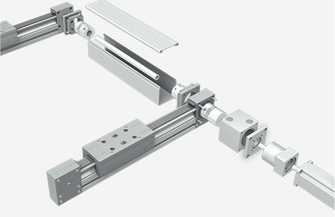
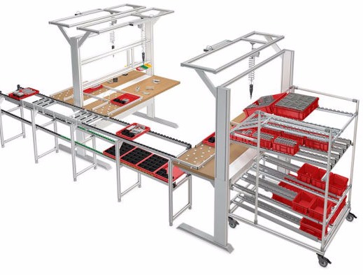
SOLID WORKS DESIGNS FOR:
• Aluminum Assemblies
• Motion Projects
• SubAssembly Drawings
AUTOCAD DESIGNS INCLUDE:
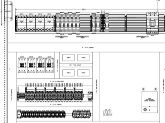
• Control Cabinet Layouts
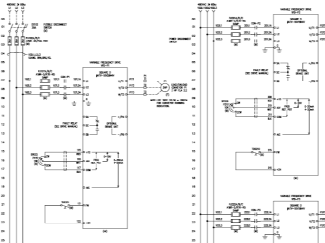
• Panel Schematic Drawings
• BOM Parts Selection
Our CAD engineering department generates a full documentation and BOM package used in the management of the project
Drawing packages from conceptual sketches or allow our engineering team to assist with a complete control system using the latest CAD software from AutoCAD®. We pride ourselves with being able to bring expertise, focus, and depth to all of your control concepts and needs. Large or small systems are welcomed and each documentation package generated contain details to assist engineers, electricians, technicians, and plant personnel using NFPA along with industrial standards for UL508A and UL698A where applicable.
• Power Wiring Diagrams
• VFD Wiring Diagrams
• E-Stop & Safety Control Diagrams
• PLC Wiring Diagrams
• Communication Diagrams
• Field Device Diagrams
• And Much More
• Your Standards or Ours
From detailed panel assembly diagrams, Machine or Conveyor layouts we will add electrical details if required to assist engineers, electricians, technicians, and plant personnel with installation or the assembly process.
• Enclosure Door Details using Manufacturer parts
• Sub-Panel Details using Manufacturer parts
• Extensive Part Libraries used to accurately represent customer needs
• Field Device Diagrams (Conveyors, Machines, Plan Views)
• Network Diagrams
• Simple Riser Diagrams
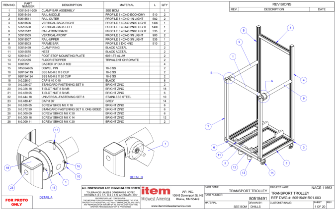
• Exploded drawing
• BOM
• Assembly Instructions
• Conceptual Designs
• Workflow Analysis
• Design Confirmation
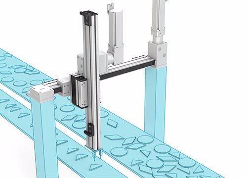
• 3D Motion Design
• Motion Control Functional Analysis
• Production Line Integration and Testing

Kim Control Systems
Minneapolis, MN
ACCESS SUPPORT DOCUMENATION AND STAY IN CONTACT